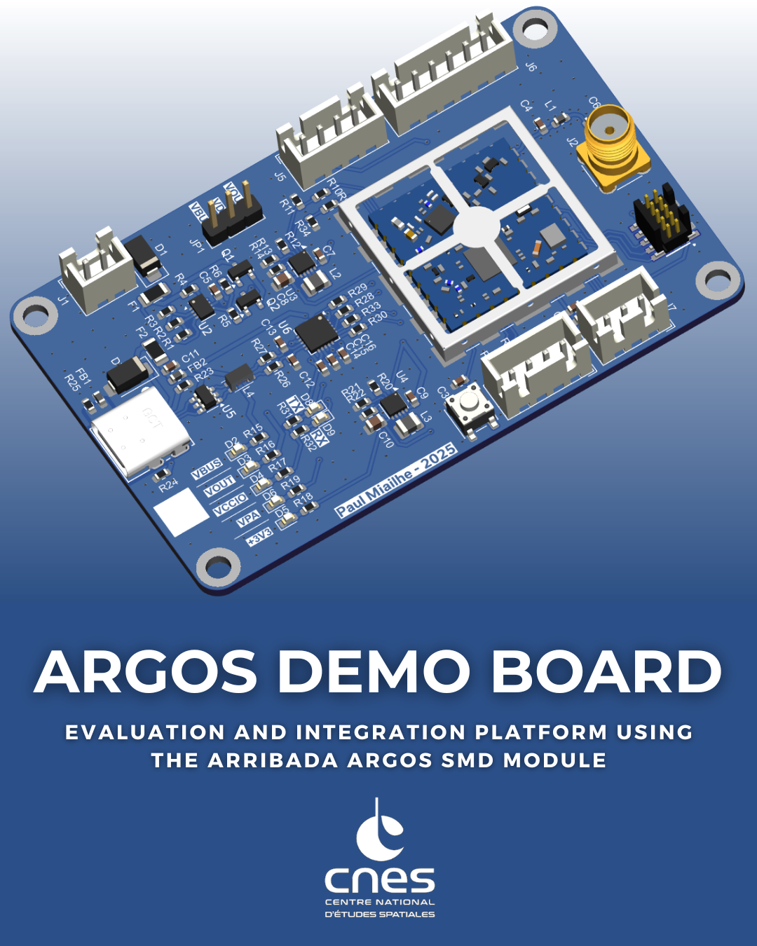
argos-demo-board
Argos Demo Board Using Arribada SMD Module
Demonstration and evaluation board designed to operate the Arribada Argos SMD module via USB and transmit ARGOS uplink messages to the Kineis satellite constellation.
© 2025/2026 CNES – Paul Miailhe.
This material is licensed under the CERN Open Hardware Licence Version 2 (CERN-OHL-S).
See licence: https://ohwr.org/licences/
Introduction
This project presents an Argos Transceiver Demonstration Board intended for the evaluation, validation, and operation of the Arribada Argos SMD module.
The board provides a compact and robust hardware platform to transmit ARGOS uplink messages to the Kineis satellite constellation using a standard USB interface.
Communication between the host computer and the Arribada SMD module is handled by a FTDI FT231XQ USB-to-UART bridge, directly interfacing with the module UART. This approach enables simple control of the transceiver using standard serial terminals or custom software tools.
The demonstration board integrates all essential functions required to operate the Arribada SMD module in a laboratory or development environment, including power supply conditioning, USB-to-UART communication, and RF interfacing. It is primarily intended to support early hardware validation, firmware development, and system-level testing of Argos communication chains prior to integration into a final embedded or avionics system.
This board targets engineers, students, and developers involved in satellite communications, avionics, IoT, or space-related applications, and may be used both as a standalone evaluation platform and as a reference hardware design.
Inline with Arribada’s open source philosophy, this board deliberately adopts a design distinct from the official demonstration hardware, focusing on simplicity and direct plug-and-play operation from a standard PC. The schematic and architecture are provided for reference, allowing potential users to reuse, adapt, or extend them according to their own needs..
Hardware Design
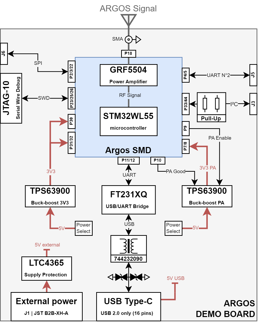
1. Communication Architecture
Communication between the host PC and the Arribada Argos SMD module is performed through the module’s UART interface.
This interface is used to send AT commands from a PC in order to configure the module and transmit ARGOS uplink messages.
→ See details on GitHub Arribada
The USB-to-UART conversion is handled by a FTDI FT231XQ USB 2.0 to UART bridge. This device converts USB data received from a virtual COM port into UART signals fully compatible with the Arribada SMD module.
This architecture allows the board to be operated using:
- Standard serial terminal software
- Custom scripts
- Dedicated test or validation tools
No additional embedded controller is required, which simplifies early testing and debugging.
2. Power Supply Architecture
The card supports two power supply modes to suit different uses.
2.1 Power Source Selection
Power source selection is performed using the JP1 jumper, which allows switching between:
- VBUS → VDD (5V) supplied by the USB-C port
- VOUT → VDD (5V) supplied via the external power input on connector J1
2.2 External Power Protection
The external power input on connector J1 is protected by:
- A resettable PTC fuse 1206L050YR
- A LTC4365 protection circuit
The LTC4365 provides:
- Reverse polarity protection
- Undervoltage protection with a threshold set to 2.5 V
- Overvoltage protection for input voltages exceeding 5 V
2.3 Power Regulation
After the protection stage, the power rail is distributed to two TPS63900 buck-boost converters:
- One converter supplies the RF power amplifier (PA) and is enabled and controlled directly by the Arribada SMD module
- The second converter is always enabled and provides the regulated 3.3 V supply required for the Arribada SMD module logic
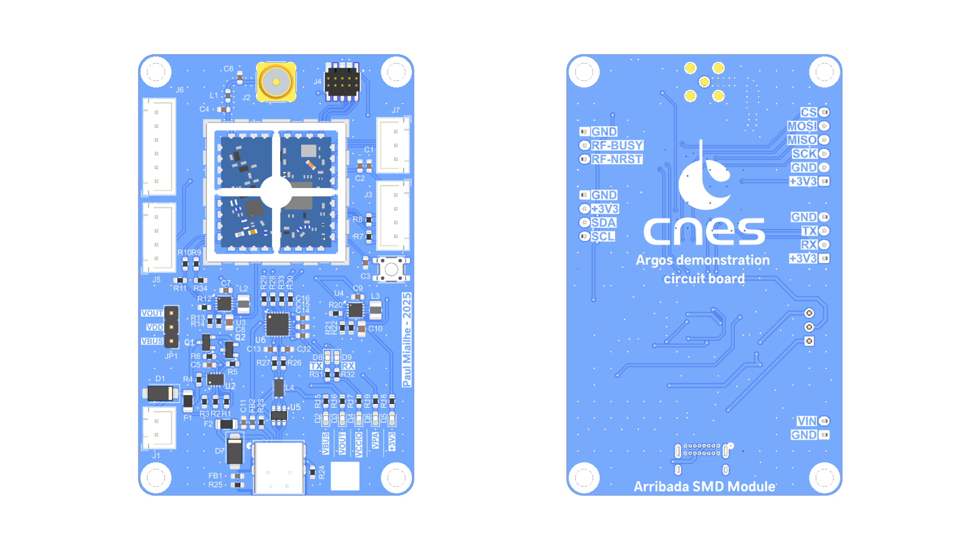
3. Connector Types
The Argos Demo Board uses the following connector families:
- USB4085-GF-A (GCT)
USB Type-C receptacle (16-pin) used for:- USB 2.0 communication with the host PC
- Board power supply via VBUS
- JST B2B-XH series
Through-hole wire-to-board connectors used for:- External power input (2.5 V to 5 V)
- Digital interfaces (UART, SPI, GPIO – 3.3 V logic)
- General-purpose I/O connections
- FTSH-105-01-L-DV-K (Samtec)
10-pin JTAG connector used for:- Programming
- Low-level debugging of the Arribada Argos SMD module
- Access to JTAG/SWD signals of the embedded STM32WL55
- 60312002114503 (Würth Elektronik)
SMA 50 Ω RF connector used for:- RF output connection
- External antenna interface for the ARGOS frequency band
- ⚠️ When transmitting, it is important to have at least a 50 Ohm load connected to the antenna output to protect against impedance mismatch.
4. Functional Diagram
Summary of the Bill of Materials (BOM)
Components used on the board, with their official datasheets:
| Reference | Part Number | Role / Function | Datasheet |
|---|---|---|---|
| D1, D7 | SMAJ15CA | TVS diode for surge and ESD protection | → Datasheet Littelfuse |
| F1, F2 | 1206L035/16YR | Resettable PTC fuse (overcurrent protection) | → Datasheet Littelfuse |
| FB1, FB2 | BLM18KG601SN1D | Ferrite bead for EMI suppression | → Datasheet Murata |
| L4 | 744232090 | Common-mode choke for USB line filtering | → Datasheet Würth Elektronik |
| Q1, Q2 | BSN20 | N-channel MOSFET for switching and protection | → Datasheet DIODES INC. |
| SW1 | PTS647 | Momentary tactile push button switch | → Datasheet C&K |
| U2 | LTC4365DDB | Overvoltage, undervoltage and reverse polarity protection IC | → Datasheet Analog Devices |
| U3, U4 | TPS63900 | Buck-boost DC/DC converters | → Datasheet Texas Instruments |
| U5 | 82400102 | Low-capacitance TVS diode array for USB protection | → Datasheet Würth Elektronik |
| U6 | FT231XQ | USB-to-UART bridge | → Datasheet FTDI |
| H4 | 3610213126S | RF shielding cabinet | → Datasheet Würth Elektronik |
| J8 | USB4085-GF-A | USB 2.0-only 16P Type-C Receptacle connector | → Datasheet GCT |
| J2 | 60312002114503 | Coaxial connector SMA | → Datasheet Würth Elektronik |
| J4 | FTSH-105-01-L-DV-K | JTAG 10-PINS | → Datasheet Samtec |
| J1, J3, J5, J6, J7 | B2B-XH | Through-hole wire-to-board connectors | → Datasheet JST |
| U1 | Argos SMD module | Transceiver Argos SMD for uplink Argos satellite | → Datasheet Arribada |
CLICK HERE TO LAUNCH THE INTERACTIVE MAP
Getting Started
- Connect the demonstration board to a host computer using a USB cable.
- Install the FTDI drivers if required.
- Select the desired power input using the JP1 jumper.
- Connect an antenna or a 50 Ω RF load to the SMA connector before powering the board.
- Open a serial terminal or a custom software tool on the host computer.
- Configure the serial port according to the Arribada Argos SMD module specifications.
- Send AT commands to configure the module and transmit ARGOS uplink messages.
- If the board is operating correctly, the 5 V and 3.3 V LEDs should be ON, and TX/RX activity LEDs should indicate serial communication.
Refer to the Arribada SMD module documentation for command syntax and operational details.
Regulatory and Operational Notice
ARGOS transmissions are subject to regulatory constraints and operational authorization.
- Transmission over the ARGOS / Kineis constellation may require prior approval
- Users are responsible for ensuring compliance with applicable regulations
- This board does not grant any transmission rights by itself
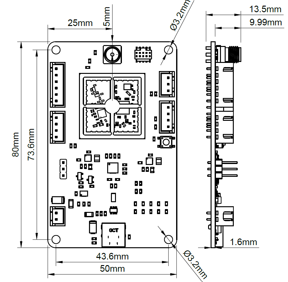
Mechanical Characteristics
- Dimensions: 80 × 50 mm
- Maximum thickness: 13.5 mm
- Mounting holes: 4 × Ø3.2 mm
- Weight without bracket: ** g**
- STEP 3D file available here:
Regulatory and Operational Notice
ARGOS transmissions are subject to regulatory and operational constraints.
- Transmission over the ARGOS / Kineis constellation require prior authorization
- Users are responsible for regulatory compliance
- This board does not grant transmission rights by itself
References & Resources
-
Arribada Initiative – Official site
See link: https://arribada.org -
Official Argos SMD Arduino Demo – by Arribada
The full Arduino-based demonstration for the Argos SMD module is available on GitHub.
See link: https://github.com/arribada/argos-smd-test-arduino -
Official Breakout Board FeatherWings – by Arribada
This breakout board can be used with a Feather board (from Adafruit) to connect the ARGOS-SMD module.
It exposes the ARGOS-SMD module pins to the Feather board and includes a dedicated LDO to power the RF amplifier.
See link: https://github.com/arribada/featherwings-argos-smd-hw -
Official Argos SMD Hardware Module – by Arribada
The Arribada Argos SMD module is a compact 20 × 20 mm PCB designed to operate as a standalone module or co-processor, enabling satellite communication via the Kineis network.
See link: https://github.com/arribada/argos-smd-hw